Working with Planes
You can add planes to a 3D view to clip objects, such as datasets, regions of interest, multi-ROIs, and meshes, along an arbitrary plane or planes. Other visual effects can also be applied to the clipped region, such as look-up table functions, edge contrast, and window leveling. In addition, the explosion options lets you sectionalize 3D renderings to reveal the interior of a sample.
Plane in 3D view

The following video provides a short tutorial about working with planes.
Planes Tutorial (7:14)
You also view this video and others on our YouTube channel (https://www.youtube.com/channel/UCuFl2zHcyStR2RJpMXbi6ow).
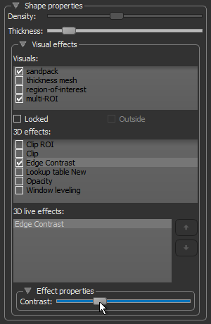
As is the case for all other shapes, you can choose the visual effects for the selected plane that you want to apply to selected visuals in the Visual effects box, shown below.
Shape properties

The following properties and visual effects are available for applying to image data, regions of interest, multi-ROIs, and unstructured grids.


The options in the Plane settings box on the Data Properties and Settings panel let you choose an initial orientation for the selected plane or to bind a plane to a 2D view. You can also choose to show corresponding 2D data in the scene’s 3D view, as well as apply an 'explosion' to reveal the interior of a sample.
Plane settings

| Item | Description |
|---|---|
| Orientation |
Lets you choose the initial orientation of the selected plane — along the X, Y, or Z axis.
Note As an alternative, you can choose to bind the plane with a view. |
| Solid |
If selected, makes the selected plane semi-solid in order to view the full area covered by the plane, as shown below.
|
| Show data |
If selected, data from the corresponding 2D view will be shown on the clipped plane in the 3D view. Note You must apply clipping in conjunction with 'Show data' (see Shape Properties). |
| Show grayscale |
Applies a grayscale LUT on the clipped plane in the 3D view and lets you adjust the center and width values independently of the window leveling values applied to the dataset.
In some cases, this may provide better results than the 'Show data' method that is also available in Dragonfly. A comparison of the 'Show data' and 'Show grayscale' options is illustrated below, in which a plane with the Show data option applied is shown on the left and with the Show grayscale option on the right.
|
| Explosion |
Lets you 'explode' 3D renderings to reveal the interior of a sample. You can choose the type of explosion — Translation, Rotation (hinge), or Rotation (screw) — in the drop-down menu, as well as the degree of translation or rotation with the Explosion slider. You can also choose to apply the effect on the left or right side of the plane and to invert rotation explosions.
An exploded 3D rendering is shown in the illustrations below. The dataset exploded by 'Translation' is shown on the left and by 'Rotation (screw)' on the right.
Note You can include exploded views in animated sequences and generate high-resolution images with this visual effect. |
| Bind with view |
Lets you link the selected plane to a 2D view. In this case, the controls available in the 2D view, such as the 3D Cursor, can be used to manipulate the plane.
Note The option to bind a plane with a view is dependent on the number of MPR views in the current scene (see Scene Layouts and Views for information about selecting a scene view that includes 2D views). |


Refer to the following instructions for information about adding and editing planes.
- Make sure that the scene in which you are working includes the 3D view.
You should note that working in a scene with all three MPR views will let you bind a plane to any 2D view.
- Do one of the following:
- Click the Plane
 icon on the Shapes panel to add a new plane to the Data Properties and Settings panel.
 - Click the Multiple Planes
 icon on the Shapes panel to add up to three new planes to the Data Properties and Settings panel. The number of planes that will be added is equal to the number of 2D views in the current scene.
- Click the Plane
- Select the required plane in the Data Properties and Settings panel and change its visibility in 3D, if required.
The visual plane and its control handle appear in the 3D view.
- Choose an initial orientation for the plane or bind the plane with a 2D view, optional.
- Adjust the plane as required.
- Drag either end of the plane handle to adjust its angle.

Note The object in the illustration above was clipped for clarity. Clipped must be selected as a visual effect to be applied.
You can also adjust the angle of a bound plane by dragging the Angle marker on the 3D cursor in the MPR views of the dataset (see Using the 3D Cursor).

- Drag the handle to translate the plane along the selected angle.

You can also translate bound planes by scrolling the associated 2D view or by dragging the 3D cursor in the MPR views of the dataset (see Using the 3D Cursor).
- Drag either end of the plane handle to adjust its angle.
- Check the Show data or Show grayscale option for the selected plane, optional (see Shape Properties).
If selected, data from the corresponding 2D view will be shown on the plane in the 3D view.
-
Reveal the interior of a sample by applying an 'explosion', optional (see Shape Properties).
- Select the visuals to which you want to apply the visual effects to.
To apply an effect, check the required object(s) in the Visuals list in the Shape properties panel.

- Select the required effect(s) and adjust their associated properties, as required (see Shape Properties).
Note You can apply the selected effects to the outside or inside of the visual plane by checking or unchecking the Outside option.
- Lock the plane in the 3D view by checking the Locked option, recommended.


