CT Rotation Finder
You can choose from a number of algorithms to find the rotation center offset for reconstructing cone-beam and parallel-beam projections in the CT Rotation Finder dialog. You can also preview the results computed from different offsets.
Open the CT Rotation Finder dialog, shown below, by clicking the Find Rotation Center button in the CT Reconstruction dialog.
CT Rotation Finder dialog

Image metrics — Shannon entropy and Sharpness — are available to find the rotation center for both cone-beam and parallel-beam projections.
CT Rotation Finder dialog

-
Enter or import the acquisition parameters for the projection that you want to reconstruct in the CT Reconstruction dialog.
-
Click the Find Rotation Center button.
The CT Rotation Finder dialog appears.
-
Select Image metric as the method in the CT Rotation Finder dialog.
-
Select a metric type — Shannon entropy or Sharpness — in the Metric type drop-down menu.
-
Click the Refresh button to compute a metric cost function vs. rotation center offset curve, recommended.
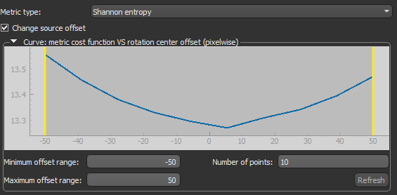
Note If required, you can adjust the minimum and/or maximum offset ranges, as well as the number of points, before you compute the curve.
-
Set the Minimum and Maximum offset values (pixel-wise) to an optimal range, recommended. Adjustments can be made on the curve by dragging the thresholds, as shown below, or by entering new values in the Minimum and Maximum Starting offset range boxes.
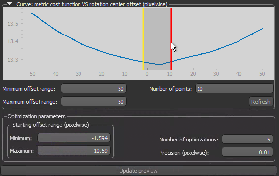
Note You can modify the Number of optimizations and Precision (pixel-wise), if required.
-
Click the Update Preview button to compute the optimal center of rotation.
After the computation is complete, a preview of the result appears in the dialog.
-
Examine the preview with the Preview tools, recommended, and then do one or more of the following:
-
Click the Compare Histogram button to compute and evaluate the histogram(s) of the generated preview(s) in the Compare Histograms dialog.
Click the Export Preview button to export the preview and its settings. You can import the inputs from the best preview in the CT Reconstruction dialog.
-
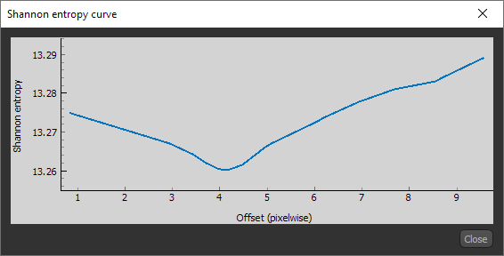
Click the Shannon Entropy Curve or Sharpness Curve button to plot the curve of the selected Image metric vs. the offset within the computed range, as shown below.
-
Select Manual range as the method and then generate additional previews centered on the found value.
-
-
Click the OK button at the bottom right of the dialog to apply the computed rotation center offset value.
Note For cone-beam projections, the Detector offset value for the X-axis will be updated with the new value in the CT Reconstruction dialog. This value will computed with the image spacing of the dataset. For parallel-beam projections, the value for the Rotation center offset will be updated as is.
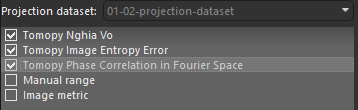
Three TomoPy algorithms — Nghia Vo, Image Entropy Error, and Phase Correlation in Fourier Space — are available to find the rotation center offset for parallel-beam projections.
CT Rotation Finder dialog.

| Algorithm | Description |
|---|---|
| Tomopy Nghia Vo |
Finds the rotation axis location using Nghia Vo’s method.
Reference |
| Tomopy Image Entropy Error |
Finds the rotation axis location using using image entropy as the error metric and the 'Nelder-Mead' routine of the SciPy optimization module as the optimizer. Reference |
| Tomopy Phase Correlation in Fourier Space |
Finds the rotation axis location by computing the offset between the first projection and a mirrored projection 180 degrees apart using phase correlation in Fourier space. The 'phase_cross_correlation' function uses cross-correlation in Fourier space, optionally employing an upsampled matrix-multiplication DFT to achieve arbitrary subpixel precision.
Reference |
-
Enter the acquisition parameters for the parallel-beam projection that you want to reconstruct in the CT Reconstruction dialog.
-
Click the Find Rotation Center button.
The CT Rotation Finder dialog appears.
-
Select one or more of the available Tomopy methods in the CT Rotation Finder dialog, as shown below.
-
Click the Refresh button to compute a metric cost function vs. rotation center offset curve, recommended.
Note If required, you can adjust the minimum and/or maximum offset ranges, as well as the number of points, before you compute the curve.
-
Set the Minimum and Maximum offset values (pixel-wise) to an optimal range, recommended. Adjustments can be made on the curve by dragging the thresholds, as shown below, or by entering new values in the Minimum and Maximum starting offset range boxes.
Note You can modify the Number of optimizations and Precision (pixel-wise), if required.
-
Click the Update Preview button to compute previews of the rotation center offsets for the selected method(s).
-
Examine the preview with the Preview tools, recommended, and then do one or more of the following:
-
Click the Compare Histogram button to compute and evaluate the histogram(s) of the generated preview(s) in the Compare Histograms dialog.
Click the Export Preview button to export the preview and its settings. You can import the inputs from the best preview in the CT Reconstruction dialog.
-
Click the Shannon Entropy Curve or Sharpness Curve button to plot the curve of the selected Image metric vs. the offset within the computed range, as shown below.
-
Select Manual range as the method and then generate additional previews centered on the found value.
-
-
Select the best preview and then click the OK button at the bottom right of the dialog to apply the computed rotation center offset value.
Note For parallel-beam projections, the value for the Rotation center offset will be updated as is.
Image metrics — Shannon entropy and Sharpness — are available to find the rotation center for both cone-beam and parallel-beam projections.
-
Enter or import the acquisition parameters for the projection that you want to reconstruct in the CT Reconstruction dialog.
-
Click the Find Rotation Center button.
The CT Rotation Finder dialog appears.
-
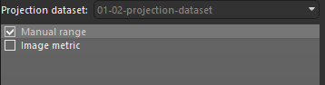
Select Manual range as the method in the CT Rotation Finder dialog, as shown below.
-
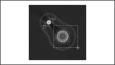
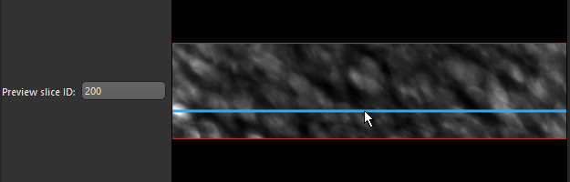
Select a slice to preview, optional.
You enter a slice number in the Preview slice edit box, or use the scroll bar to set the slice number, as shown below.
-
Select a Starting offset value, a Step size, and an Ending offset value.
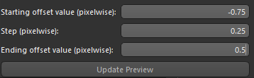
Note A maximum of six previews can be computed. The set starting offset value, step, and ending offset value cannot result in more previews.
-
Click the Update Preview button to compute the selected preview.
After the computation is complete, the previews appear in the dialog.
-
Examine the preview with the Preview tools, recommended, and then do one or more of the following:
-
Click the Compare Histogram button to compute and evaluate the histogram(s) of the generated preview(s) in the Compare Histograms dialog.

-
Click the Export Preview button to export a preview and its settings. You can import the inputs from the best preview in the CT Reconstruction dialog.
-
Generate additional previews centered on the best value.
-
-
Select the best preview and then click the OK button at the bottom right of the dialog to apply the computed rotation center offset value.
Note For cone-beam projections, the Detector offset value for the X-axis will be updated with the new value in the CT Reconstruction dialog. This value will computed with the image spacing of the dataset. For parallel-beam projects, the value for the Rotation center offset will be updated as is.

The tools at the top of the dialog let you to pan, zoom, and reset the preview(s).
| Item | Icon | Description |
|---|---|---|
| Reset |
|
Resets the original view of the preview(s). |
| Pan |
|
Pans or zooms the preview(s) as described below. Pan… Click with the left mouse button and then drag to pan the preview. Zoom from clicked point… Click with the right mouse button and then drag up and down to Zoom in and Zoom out from the clicked point. |
| Zoom |
|
Zooms to a drawn rectangle, which can be defined by dragging your cursor over the area that you want to zoom.
|